

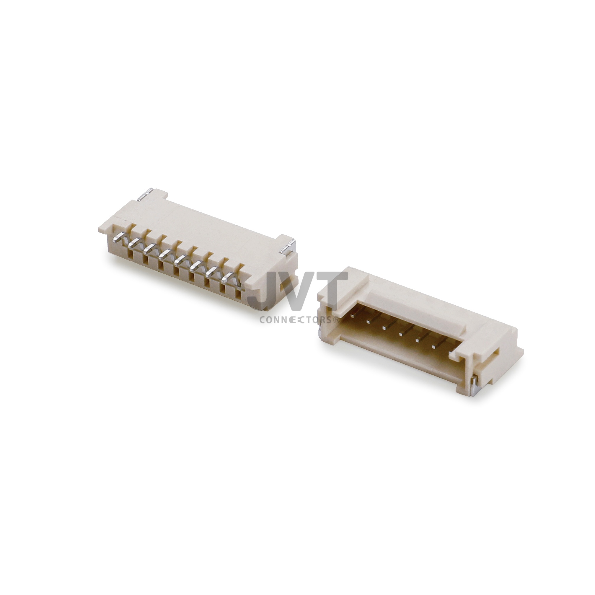
The energy storage bms connector selected for a residential battery board quietly decides how much PCB area the project has to give up before a single cell is chosen. On a home ESS control board we worked on with a listed energy storage integrator, that decision had already been made for them by the original Bill of Materials, and the mechanical enclosure was fixed. The board had to read sixteen cell groups through a balancing harness, feed the main control electronics from the battery bus, and survive a continuous charge and discharge duty cycle for years inside a wall-mounted cabinet. Two separate imported connectors were doing that job, and together they were pushing the layout past the edge of the available board area.
This case study walks through what the project actually required, why the customer asked us for a drop-in alternative, what we specified, and the results that came out of the build. It is written for hardware engineers and procurement teams who are specifying connectors for home battery systems and want to understand where the real constraints sit.
What an Energy Storage BMS Connector Has to Survive
A battery management board is not a consumer device board. It sees a duty cycle that never really stops: charge in the morning, hold through the afternoon, discharge into the evening, and repeat for years. Every one of those cycles produces a small thermal expansion and contraction in the housing and the terminals, and the connector is the one component that has to absorb that movement while keeping contact resistance low.
The customer's specification listed three functional jobs for the interface, and each one pulls the design in a different direction.
- Cell balancing harness. Low current, but many positions. Sixteen cell groups means a lot of separate signal paths, and each path has to stay stable enough for the BMS to read millivolt differences.
- Main power input. Higher current than the harness, thicker insulation on the wire, and a terminal geometry that will not heat up under sustained load.
- Assembly and service. The harness is plugged in on the production line, and the same interface has to survive being unplugged and reconnected during field service without losing retention force.
On top of the electrical requirements, the enclosure is a sealed plastic box with limited internal volume, and the safety file requires the plastics to be flame retardant. UL 94 V-0 is the usual target for the housing material in this application, and it is a material property rather than something a connector gains from being wired correctly. RoHS and REACH compliance matters as well, because these units are shipped into Europe and North America.
Why the Customer Wanted to Replace the Imported Part
The original design used an imported part number from a large connector brand. There was nothing wrong with the connector itself; the problem was everything around it. Lead time moved around unpredictably, the minimum order quantity pushed the customer to hold stock they did not want, and a design change on the harness side took a full revision cycle to confirm because the original supplier would not share detailed mating dimensions.
The question the engineering team asked us was narrow and practical: could we supply an equivalent part that keeps the same PCB footprint, so nobody has to touch the board layout? That is the cross-reference conversation we have with customers constantly, and the answer depends on three checks that we run before quoting anything.
- Footprint check. Contact positions, pitch, row count, and the drill pattern have to line up so the existing solder pads stay valid.
- Mating check. The header and housing interface, including latch position and polarization keys, has to match the wire side.
- Duty check. The replacement has to be comfortable at the continuous current and the temperature the board actually sees, not just at the catalogue rating.
Because the customer was replacing a part rather than designing a new one, the qualification path was short. We supplied drawings, sample connectors, and terminal cross-sections, and their team ran the comparison on their own test bench. This is the standard route for a localization substitution project: the customer keeps ownership of the verification, and we provide the data they need to run it.
What We Specified for This Energy Storage BMS Connector
Rather than finding two separate replacements, we proposed collapsing the interface onto one wire-to-board family available in both 2.00 mm and 2.54 mm pitch. That single decision removed one component, one footprint, and one line item from the BOM.
Signal side: 2.00 mm pitch, double row
The balancing harness moved to a double-row 2.00 mm pitch configuration. Two rows halve the length of the connector along the board edge compared with a single-row equivalent, which is where the board area came back. Double-row layouts also keep the harness bundle narrower, which matters when the cable runs past the battery modules.
Power side: 2.54 mm pitch with locking latches
The main power input stayed on 2.54 mm pitch, which is the natural choice for this board because the customer already had tooling for that pitch and the larger contact geometry handles the current comfortably. We specified a version with locking latches and a polarity key so the harness cannot be pushed onto the header the wrong way round on the production line.
Terminals: plated to hold contact resistance
Contact resistance is the number that degrades first in a cycled battery application. Terminal plating and the normal force designed into the contact spring do the work here, and both were part of the specification rather than an afterthought. The customer's own bench data on the incoming samples covered low contact resistance under repeated cycling, which is the measurement that matters for a board that cycles every day.
Configuration summary for this project
Signal path: 2.00 mm pitch double-row wire-to-board, multi-position, for the cell balancing harness.
Power path: 2.54 mm pitch wire-to-board with locking latches and polarization for the main control board input.
Housing material rated UL 94 V-0, RoHS and REACH compliant, suitable for export certification files.
Supplier position: JVT manufactures the connector; the customer keeps the qualification decision and the test data.
Project Results After the Change
The customer completed the changeover on their own schedule and reported the outcome back to us. The published figures for that project are listed below; they describe this specific build, not a general performance claim.
| Item | Before the change | After the change |
|---|---|---|
| Connector interfaces on the board | Two imported part numbers | One JVT two-pitch family |
| Lead time in that project | Baseline | Halved |
| Housing flame rating | UL 94 V-0 required | UL 94 V-0 material supplied |
| Layout impact | Two footprints | One footprint, area returned to the layout |
| Export documentation | TUV and UL files pending | Materials data available for the customer file |
The engineering team also reported that the double-row signal connector changed how the harness is built. With both rows on one interface, the wire bundle leaves the board in a single direction instead of splitting into two runs, which simplified the harness drawing and reduced the number of cable ties inside the cabinet.
Why Choose JVT as Your Long-Term Interconnect Partner?
JVT is the brand of Dongguan JVT Connectors Co., Ltd., a connector manufacturer established in Dongguan, Guangdong in 2006, with a 6,500 square metre plant and a branch in Wujiang, Jiangsu. We design and manufacture connectors rather than trading them: injection moulding, stamping, and automatic pin insertion all run in house, supported by more than twenty injection moulding machines, more than twenty stamping presses, and more than fifty automatic pin insertion machines, alongside an in-house engineering team and a quality management system.
Our management systems are certified to ISO 9001, ISO 14001, IECQ QC080000, and IATF 16949, and our products are tested by UL and SGS. Our pitch coverage runs across nineteen steps from 6.35 mm down to 0.60 mm, and our application ranges include automotive, low-altitude flight, lithium battery 3C, power tool, power module, industrial, consumer, new energy, home appliances, and computer. Our product families include wire-to-board, wire-to-wire, board-to-board, IDC, pin header, DC connectors, board-in terminals, FFC/FPC, and the terminal series (187, 250, and 110 quick-connect terminals, soldering terminals, substrate terminals, direct plug, and straight-through terminals).
Much of our work is localization substitution: replacing imported connectors with parts made in our own plant. Where a customer's design already uses a Molex, JST, TE, HRS, or AMP part number, we approach it as a cross-reference exercise and supply the drawings and samples needed for the customer to verify equivalence on their own bench. That is how we were introduced to this energy storage project, and it is the same route we follow for automotive, industrial, and appliance boards. To see the families used on battery and solar equipment, start from our new energy connector range and the wider wire-to-board connector catalogue, then look at the 2.00 mm pitch and 2.54 mm pitch series that were used here.
Frequently Asked Questions About the Energy Storage BMS Connector
What is an energy storage BMS connector used for?
It is the interface between the battery management board and the rest of the system. In a home ESS it normally carries two things: the cell balancing harness that lets the BMS read each cell group, and the main power input that feeds the control electronics from the battery bus.
Can a JVT part replace a Molex connector without changing my PCB?
In many cases yes, provided the contact positions, pitch, row count, drill pattern, and latch geometry line up. We treat this as a cross-reference exercise: we supply drawings, samples, and terminal data, and your team confirms equivalence against the original part on your own bench. We are an independent connector manufacturer and not an authorised distributor of any imported brand.
Which pitch should I choose for a cell balancing harness?
It depends on position count and available board edge length. A double-row 2.00 mm pitch layout compresses a multi-position harness into roughly half the edge length of a single-row equivalent, which is why it was the right answer on this board. Where the customer already has tooling or a wider board, 2.54 mm pitch remains a comfortable choice.
Does a battery connector housing need a UL 94 V-0 rating?
UL 94 V-0 is the flame rating that appears most often in residential storage specifications, because the plastic sits next to cells that can vent. It is a property of the housing material, so it has to be confirmed from the material specification rather than assumed from the connector drawing alone.
How do I get samples for a residential ESS project?
Send us the board drawing, the current per contact, the operating temperature range, and the wire gauge you intend to use. We will come back with a recommended family, the matching terminal, and samples for your bench test. Where a fit and function check against an existing part number is needed, include that part number in the request.
If your board is short of space and the imported part keeps moving its lead time, the fastest way forward is a footprint comparison. Send us the drawing and we will tell you within days whether an energy storage bms connector from our 2.00 mm or 2.54 mm families can drop in without a layout revision.
Review the New Energy Connector Range Request a Footprint Cross-Reference